The "Problem"
Last January, Vidado moved out of our beautiful office on the 24th floor of 2020 Harrison Street on Lake Merritt and into a more appropriately sized, cozy brick building in Jack London Square. This is where we are now. The building has character and charm. The building has plants on the wall and a ping-pong table downstairs. The building has a dedicated parking lot with a remote controlled gate to allow access for employee vehicles.
At any given time, there are \(d\) people who drive to the office and need to park. We have \(r\) remote controllers for the gate, where \(r\lt d\). This means that \(r-1\) remotes are distributed among the drivers, and one remote stays upstairs in the office. When one of the \(d+1-r\) unlucky drivers without a remote arrives in the morning, they post an @here message in the office Slack channel and ask to be let in, and someone stands up, walks over to the resident office remote, hits the button, and lets the driver into the parking lot. I'm an early riser, so that person letting them in has often been me, but eventually I started thinking, "shouldn't some kind of robot be doing this for me?" I took the mild inconvenience as an excuse to work on a fun hardware side project. This blog post details some of the thought process and pitfalls of making your simplest possible first robot.
Walking to the window to manually open the gate.
Roughing a Design
My mental model of a remote control is something like this.
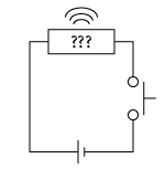
There's a battery, a button, and a collection of other stuff including a microwave emitter. Pushing the button applies some voltage somewhere, and this triggers the emitter, which opens the gate to the parking lot. My first thought was to wire up some other piece of hardware (a transistor?) to apply the voltage that triggers the microwave emitter. That would require disassembling the remote, but it would also allow me to replace the battery with some more permanent source of voltage, like the wall.
In the end, I ditched that idea, because the remote already has a well-defined user interface, which is the button, and I know how to push a button, and if I can properly build a button pusher, I will likely find other buttons to push in the future -- it's a pretty ubiquitous interface! I thought I'd probably need two pieces of hardware -- one part that moves and actually hits the button, and another to hold the software and tell the other part what to do and when.
Choosing the Parts
I knew that I needed the whole thing to be accessible via Slack, and I figured I would be writing some amount of custom Python to drive it, so I went with the Raspberry Pi Zero W. It has a WiFi chip built in, runs a Debian spinoff, and at the time of writing this, it's $10 for the board. I splurged and got a slightly pricier kit off of Amazon that comes with a power supply, a heat sink, cases, and some cable adapters for USB and HDMI.
For the button pushing component, I originally planned to get a linear servo, because that's what best replicates the motion of a human finger poking something, but I suggested the idea to a mechanical engineer friend of mine, and he said, "I just feel like linear servos don't have a very satisfying actuation curve." I don't know what that means, but it was a strong enough sentiment for me to settle on a positional rotation servo. I picked up a HS-425BB servo from a local hardware store. The specs sheet lists the driving voltage in the 5V-6V range and the no-load current draw under 200mA. I know that the Pi takes 5V input and that the power supply included in the kit can output 2.5A, so there seem to be no issues there. I didn't want to have to use a second power supply just for the servo.
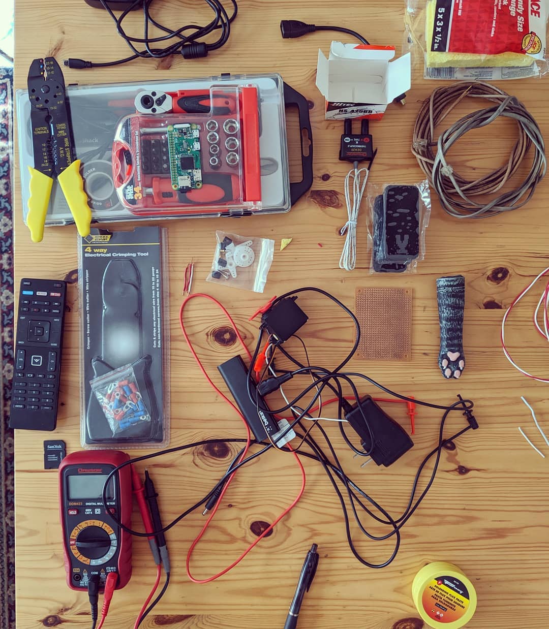
This is what my living living room table has looked like for a couple of months now.
Powering the Servo and Board
The first issue that came up is that I wanted to use one power supply to drive both the servo and the board. The power supply included in the kit connects directly to a USB micro port on the Pi. I read on StackOverflow that the board has some sort of overcurrent protection (like a fuse) on the USB port that powers the board. I didn't want to have to worry about how much current the servo would draw through that particular point, and I had also read that the board's GPIO +5V rail is the same contact point as whatever powers the rest of the board, so I ended up cutting the USB connector off of the power supply cable, and clipping the stripped hot and ground wires directly to the GPIO rails, essentially bypassing the fuse. After doing this, plugging in the power supply made the board turn on. The board doesn't have any on/off switch. It's either powered, or it's not. I also soft attached the servo's positive and negative contacts to equivalent high and low GPIO rails.
Getting Servo Movement
Installing an Operating System
The Pi Zero W by default doesn't come with an OS installed, or even a device for persistent storage, which I didn't realize when ordering it. I picked up a 16GB SanDisk micro SD card and followed some online instructions to install NOOBS, which is the version of Raspbian with all of the bells and whistles.
The installation process went fairly smoothly up until the end, when allowing Raspbian to run a complete set of updates somehow caused the device not to be able to boot anymore. The board just blinked lights in some pattern that StackOverflow revealed meant that the filesystem on the SD card was no good. I started the process over and did not allow the OS to update after installation. This resulted in a situation where the OS would boot fine (according to the board lights) but wasn't able to output any video through HDMI. Some more Googling, and some fiddling with the OS settings in safe mode eventually cleared this issue, and I was able log into the OS proper.
Outputting a Signal
The next thing you would want to do is get the servo to make some movement. In addition to positive voltage and ground leads to power the device, the HS-425BB has a third connection point for telling it what to do. The idea is that you apply a pulse width modulated (PWM) signal to this wire. That signal has some amount of up time (called the duty cycle), when it's at a positive voltage, and some amount of 0 voltage down time, and the servo interprets this as an absolute position and moves there. The duty cycle maps linearly to the absolute positions available to the servo.
NOOBS has a bunch of convenience software pre-installed, including the Python modules required to generate a PWM output on some pin. My first attempt looked something like this, although the exact numbers may vary. Only some of the GPIO outputs are capable of producing the PWM signal, and I arbitrarily chose pin 12.
import RPi.GPIO as GPIO
from time import sleep

pin = 12
frequency = 50
pause_seconds = 2

GPIO.setmode(GPIO.BOARD)
GPIO.setup(pin, GPIO.OUT)

pwm = GPIO.PWM(pin, frequency)
pwm.start(5)

try:
    while True:
        pwm.ChangeDutyCycle(45)
        sleep(pause_seconds)
        pwm.ChangeDutyCycle(5)
        sleep(pause_seconds)

except KeyboardInterrupt:
    pwm.stop()
    GPIO.cleanup()
You can see above that the RPi module is doing the heavy lifting. The important input parameters are a pin number, a signal frequency, and a duty cycle. For this library's interface, the duty cycle is specified in a percent of the full cycle. In this case, 0 would mean no duty cycle, and 100 would mean a full duty cycle of \(1/(50\text{Hz}) = 20\text{ms}\). Note that different devices may or may not actually have any meaning attached to duty cycles of these specific durations. Devices may differ in their signaling specifications. The sleep statements are in the above script, because RPi has no idea when the servo is done moving. The servo doesn't return any information about its state (it just has the 3 wires), so you just have to continue sending a signal for some duration and hope that the movement is complete before generating the next signal. Running the above script resulted in finally getting some movement out of the servo, which was very exciting!
There was just one problem. Although it's not in the GIF above, the servo jittered significantly when it was supposed to be holding still (during the sleep statements). It bounced back and forth maybe +/-3 degrees around the position it was trying to hold. It was a dramatic effect. You could see it. You could hear it. This is actually something that's addressed in the RPi documentation. They are apparently generating the output signal in software, and the Python garbage collection and kernel thread scheduler cause the pulse width to be very inconsistent. There's a similar library called pigpio, which is apparently written at a lower level and uses the Pi's hardware to generate a more consistent PWM signal. Unfortunately, it has a slightly different interface. Here's what the test code looks like using that module.
import pigpio as io
from time import sleep


pause_seconds = 2
GPIO_pin_12 = 18

pi = io.pi()

def move_to(x):
    pi.set_servo_pulsewidth(GPIO_pin_12, x)

def run():
    while True:
        move_to(1350)
        sleep(pause_seconds)
        move_to(2350)
        sleep(pause_seconds)


if __name__ == '__main__':
    run()
There are a few things to note about this test script. The first is that it uses a different scheme called BCM for numbering the pins, so what I believe to be pin 12, it believes to be pin 18. Debugging to discover that fact was a frustrating experience. The next thing to note is that set_servo_pulsewidth doesn't take a percent of the full timing period to set the duty cycle to, but rather accepts the duty cycle in absolute microseconds. The specs sheet for the HS-425BB says that it understands widths between 553 and 2520 microseconds. I don't necessarily think it's nice or convenient to debug code that's all microseconds and sleeps, so the next step was to wrap this in a convenient interface.
Wrapping the Servo Interface
I wanted to write something that was as simple as possible while still being reusable for other servos, as I plan to make other toy projects in the future. The wrapper class that I threw together accepts a pared down version of a servo specifications sheet to expose a nice interface. The servo's minimum and maximum allowed pulse widths, in conjunction with its range of motion, can be used to convert positional degrees to pulse width microseconds. The servo's angular speed can be used to determine how long a given movement should take and block for that amount of time. I also wanted to forget about the whole GPIO BCM pin numbering thing. This is the test code from above, written using the convenience class.
from simple_pi_servo_wrapper import Servo


def run():
    servo = Servo('specs.json', pin_num=12, use_GPIB_index=True)
    while True:
        servo.move_to_position(-30)
        servo.move_to_position(30)


if __name__ == '__main__':
    run()
Isn't that nicer?? The input position here is degrees of rotation from the middle point -- the servo can move from -90 to +90 degrees. I've been told by hardware buffs that this is a perverse mapping, and that the standard mapping has its minimum position at 0 degrees, but this is my project, and I'll map it symmetrically if I want to.
Creating a Generic Slack Bot
Again, I wanted to write something that would be convenient and reusable. I modeled the bot off of argparse in a sense. You tell the bot what keywords Slack users can send to interact with it, and you give it callbacks to invoke if given the correct keyword. It has two distinct buckets of callbacks -- one for all users and one for admin users. The Slack bot's main job is to connect to your Slack instance, accept direct messages, invoke callbacks, respond to the direct message, and make sure it doesn't crash. It will also, by default, present a help menu to users who want to interact with it. There is a nice readme for the bot here, but the following is a minimal example of importing the bot and connecting to Slack.
from stateless_slack_RTM_bot import SlackBot


# Define user interaction with the bot
invocation_string = 'capitalize'
help_string = 'Returns user input but in upper case.'
def convert_to_uppercase(s):
    return s.upper()

# Create bot instance and start it
bot = SlackBot('bot_config.json')
bot.register_function(invocation_string,
                      convert_to_uppercase,
                      help_string)
bot.start()
In the specific case of my gate bot, I chose to expose only an open invocation, for opening the parking lot! For admin users, I exposed a bunch of debug features for theming the bot and setting the start and end points of the servo arm. The full code is available here.
Putting It All Together
I mounted the servo and Pi to some wood, added some Velcro, and attached the remote control. The nice thing about Velcro is that it allows the servo to be loosely coupled to the remote on contact, so there is a wider range of viable travel motions for the servo arm. This is what it looks like in action -- you send a message to the bot user on Slack, and the gate opens up.
As a reminder, here are some of the gotchas that showed up during this project.
- The Pi doesn't come with any persistent storage.
- Allowing Raspbian to update after install may corrupt your filesystem. The board light blinking 4 times at regular intervals indicates that this has happened.
- You may need to fiddle with the Raspbian settings in safe mode in order to get functional HDMI on boot. This is expected, and the settings are well-commented.
- Not all PWM-generating modules are equal. Some cause jitter in the servo.
- There are at least 2 different numbering conventions for the Pi's pinout. Different modules may prefer different conventions.
- Signaling the servo without sleeping causes it to do nothing. It needs time to move.
Special thanks to Benjamin Blasdell for helping me debug the hardware, Jake Wood for helping me cut the wood and mount the parts, and many of my coworkers for encouraging me to complete this project.